
Vapors, formed within the engine, are removed from the crankcase, gear train and valve compartment by a continuous pressurized ventilating system.
A slight pressure is maintained in the engine crankcase by the normal seepage of a small amount of air and combustion gases past the piston rings. These gases are swept up through the engine and pass through a crankcase breather. On vehicle engines the gases are then vented to the atmosphere.
Breather extension hoses may be required on certain Series 60 engines used in on-highway vehicle applications. Under certain conditions, the vapors from an operating engine may be circulated through the battery charging alternator by the alternator cooling fan. Excessive ingestion of vapors may lead to alternator malfunction. This can occur if the internal components of the alternator become coated with oil-laden dust or road grit.
To minimize the potential for this condition, check the length of the engine breather tube and add an extension hose, if necessary. For proper dissipation of vapors, the end of the breather hose must extend at least 12 inches below the oil pan rail.
A wire mesh element is located inside the valve cover, or in a separate housing on the valve cover cap or at the gear case cover. This element traps excess engine oil particles in the vapor and returns them to the crankcase. See Figure "Wire Mesh Elements" .
Note: The Series 60G automotive engine uses a closed crankcase breather system. Refer to "6.4 Closed Crankcase Breather for Series 60G Automotive Engines" for more information.
|
1. Two-piece Valve Cover Cap |
6. Baffle |
|
2. Retainer Clip |
7. Retainer |
|
3. Wire Mesh Element |
8. Valve Cover Cap |
|
4. One-piece Valve Cover |
9. Seal |
|
5. Screws |
10. Breather Housing |
Figure 1. Wire Mesh Elements
The former baffle, installed on engines between 6R128446 and 6R134254, has been replaced with the current baffle to redirect oil splash from the rocker arms. This prevents oil from contaminating the breather element.
To determine if repair is possible or replacement is necessary, perform the following procedure. See Figure "Flowchart for Repair or Replacement of Ventilating System" .

Figure 2. Flowchart for Repair or Replacement of Ventilating System
Precleaning is not necessary.
Remove ventilating system as follows:
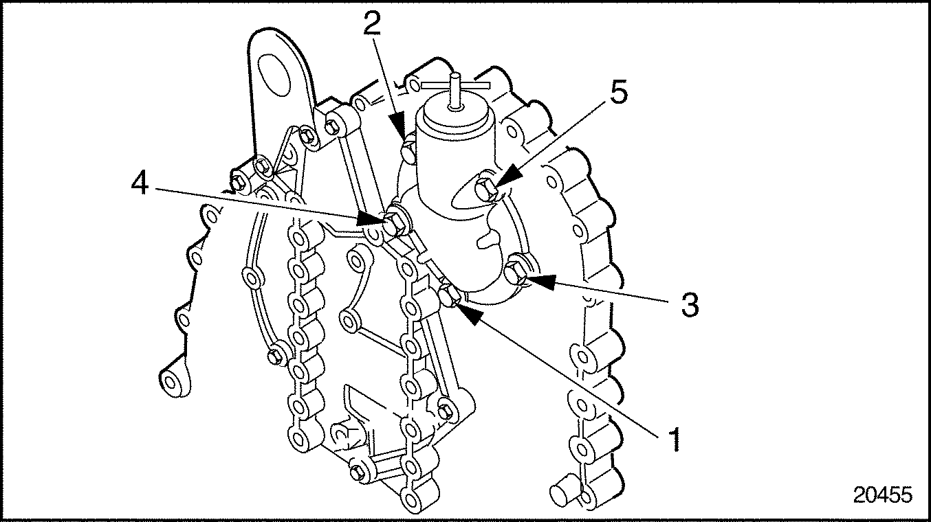
Figure 3. Breather-Oil Fill Housing Bolt Location

|
1. Breather Housing |
4. Bolts (3) |
|
2. Wire Mesh Element |
5. Bolts (5) |
|
3. Retainer |
|
Figure 4. Gear Case Cover-Mounted Breather Housing

|
1. Two-piece Valve Rocker Cover |
6. Baffle |
|
2. Retainer Clip |
7. Retainer |
|
3. Wire Mesh Element |
8. Rocker Cover Cap |
|
4. One-piece Rocker Cover |
9. Seal |
|
5. Screws |
10. Breather Housing |
Figure 5. Breather Housing-Mounted Breather
Inspect the ventilating system as follows:
Clean the wire mesh element components prior to inspection as follows:
|
EYE INJURY |
|
To avoid injury from flying debris when using compressed air, wear adequate eye protection (face shield or safety goggles) and do not exceed 276 kPa (40 psi) air pressure. |
Install the ventilating system as follows:
Note: The baffle must be installed with bolting flanges against the retainer to permit proper engine breathing.
| Series 60 Service Manual - 6SE483 |
| Generated on 10-13-2008 |