This system utilizes an engine-mounted ECM only with the EDU components of the DDEC I system contained in the ECM. The replaceable PROM is an EPROM in the DDEC II ECM. The ECM has isolator mounts for both vibration and electrical isolation. Depending upon application, some units have fuel cooling of the ECM. The engine-mounted system simplifies vehicle wiring for greater reliability.
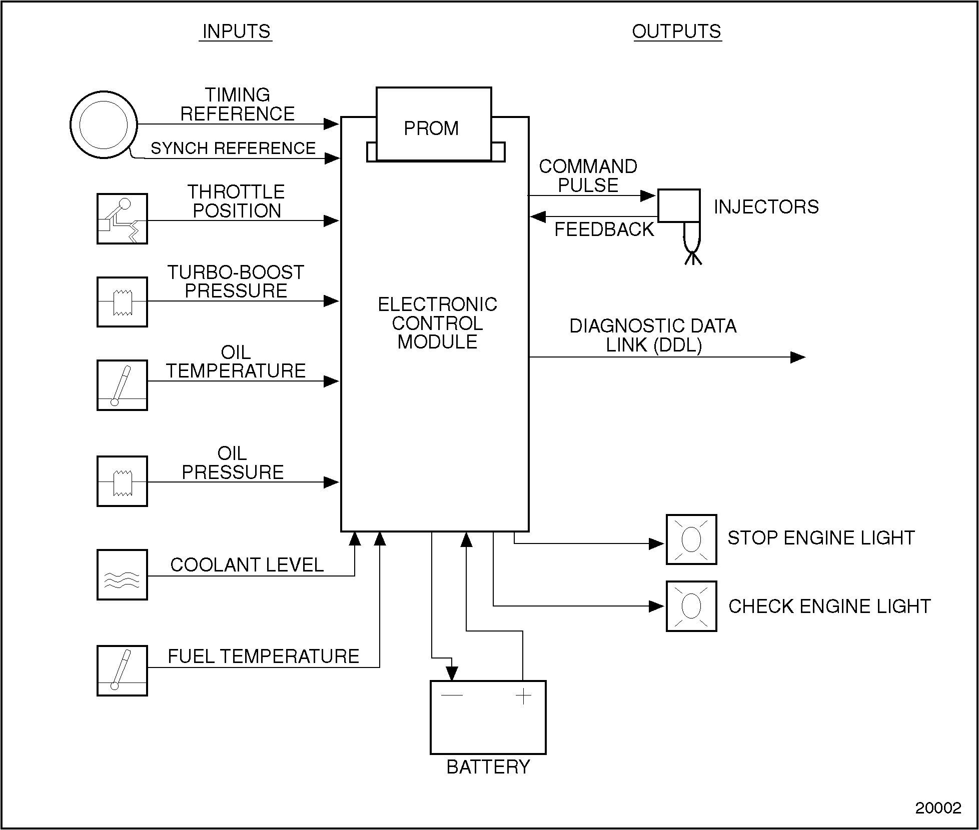
The DDEC II ECM is a microprocessor. It is the control center of the DDEC II system. See Figure "Schematic Diagram of DDEC II" .
Figure 1. Schematic Diagram of DDEC II
The DDEC II ECM is packaged in a die-cast aluminum housing with sealed connectors. See Figure "DDEC III/IV and DDEC II Electronic Control Module (ECM)" . It is mounted on the left side of the engine block.
The DDEC II consists of the following:
The DDEC II ECM is a sealed, nonserviceable unit. Tag defective ECM for recore.
Basic mechanical checks should be made beforehand to verify that the problem is definitely related to the electrical portion of the system. If the basic mechanical checks fail to locate the problem, refer the Detroit Diesel Single ECM Troubleshooting Manual, (6SE497). Start by reading the "Basic Knowledge Required" section before attempting to diagnosis electrical faults.
There are two diagnostic Data Readers (DDR) that can be used for diagnosis of DDEC I and DDEC II engines. See Figure "DDEC I & II Reader" and see Figure "DDEC II & III/IV Reader" .

Figure 2. DDEC I & II Reader

Figure 3. DDEC II & III/IV Reader
Perform the following steps for ECM removal:
Perform the following steps for ECM installation:
|
PERSONAL INJURY |
|
Diesel engine exhaust and some of its constituents are known to the State of California to cause cancer, birth defects, and other reproductive harm.
|
Using "Check Engine" light, read the DDEC II Diagnostic codes. If the diagnostic reader is not available, the following procedure can be used to read the fault codes using the "Check Engine" light on the dashboard of the vehicle. See Figure "Dashboard Warning Lights" .

Figure 4. Dashboard Warning Lights
If the vehicle is equipped with an OEM supplied diagnostic switch, hold the switch in the "ON" position. This should be done with the ignition on and the engine not running.
If there is no diagnostic switch, locate the 12-pin Diagnostic Data Link (DDL) connector (for DDEC I and II applications only) under the dash of the vehicle. See Figure "Examples of Diagnostic Data Link (DDL) Connector" .
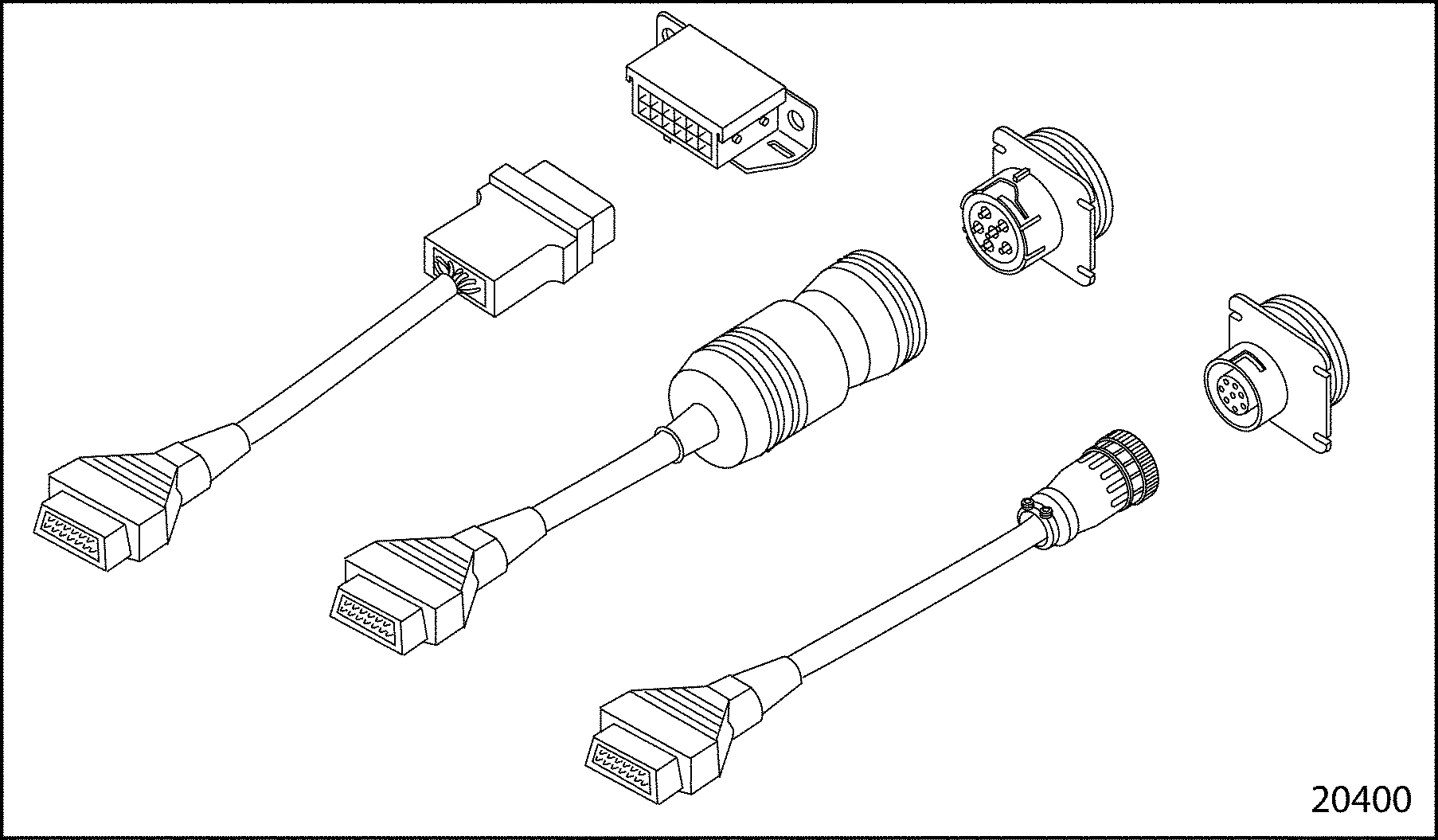
Figure 5. Examples of Diagnostic Data Link (DDL) Connector
NOTICE: |
|
If the vehicle is equipped with an OEM supplied diagnostic switch, the switch must NOT be switched on when operating the vehicle. If this is done, the diagnostic mode line will be grounded, and the throttle will be forced to the idle position, affecting vehicle operation. This condition will not occur when a diagnostic reader is used. |
These methods will cause the Check Engine light to begin flashing a code when the ignition is turned to the ON position. Code 25, for example, would be two flashes followed by a pause, followed by five more flashes. This code would indicate no trouble codes logged since the last system check. This flashing code will be repeated until the diagnostic switch is turned OFF or the jumper wire is removed from pins A and M (on DDEC II engines only). If any code(s) other than code 25 is logged, refer to the Detroit Diesel Single ECM Troubleshooting Manual (6SE497).
Fault codes can be cleared from the DDEC II and III/IV systems only by using a diagnostic reader. Follow the instructions supplied with the reader to clear the fault codes.
Note: Before beginning any repair procedures, the ignition switch must be in the OFF position.
The following tools are required to replace the former EPROM with the improved EPROM stabilizer kit:
To replace a DDEC II EPROM, see Figure "Replacement Flowchart for DDEC II EPROM" .

Figure 6. Replacement Flowchart for DDEC II EPROM
Perform the following steps to remove the former EPROM:
NOTICE: |
|
Failure to properly ground your hand while handling the ECM may result in damage to the EPROM, the ECM or both. |
NOTICE: |
|
Use care to avoid damaging the cover gasket on the ECM. A damaged cover gasket could allow contaminants to enter the ECM, which may cause damage. |
Install the improved EPROM stabilizer kit as follows:
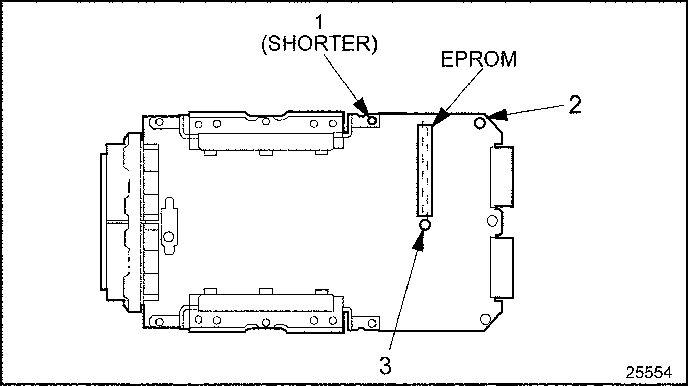
Figure 7. EPROM and Spacer Locations
NOTICE: |
|
Use care to avoid damaging the cover gasket on the ECM. A damaged cover gasket could allow contaminants to enter the ECM, which may cause damage. |
Note: If the gasket is damaged, it must be replaced with a new gasket.
The resistance of the ECM to block must be checked after installation. Use the following procedure:
| Series 60 Service Manual - 6SE483 |
| Generated on 10-13-2008 |