The centrifugal-type water pump circulates the engine coolant through the cylinder block, cylinder head, radiator and the oil cooler. See Figure
"Front Mounted Water Pump "
.
The pump is mounted on the front of the engine gear case cover on units built prior to 6R037024 and is driven by the water pump drive gear. The water pump drive gear meshes with the bull gear.
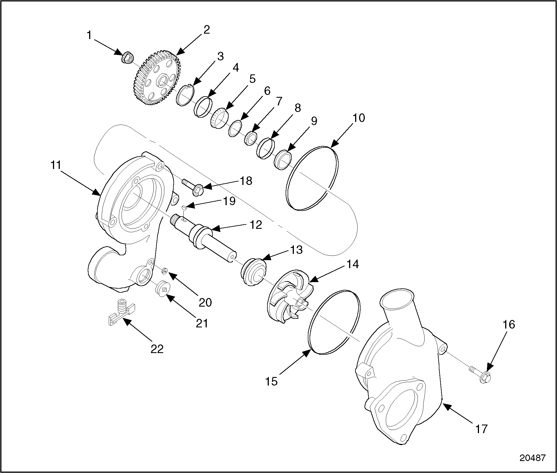
Figure 1. Front Mounted Water Pump
An impeller is pressed on one end of the stainless steel drive shaft. The other end of this shaft has internal threads, and a retaining bolt secures the water pump drive gear to the shaft. Two identical roller bearing assemblies are used to carry the shaft See Figure
"Front Mounted Water Pump Details and Relative Location of Parts "
.
1. Locknut
12. Drive Shaft
2. Gear, Water Pump Drive
13. Water Seal
3. Snap Ring
14. Impeller
4. Bearing Race
15. Seal Ring, Water Pump Cover
5. Roller Bearing, Larger
16. Bolt, Cover-to-housing
6. Spacer Rings (2)
17. Water Pump Cover
7. Roller Bearing, Small
18. Bolt, Pump Housing to Gear Case Cover
8. Bearing Race
19. Woodruff Key
9. Oil Seal
20. Small Pipe Plug, Water Pump Housing
10. Seal Ring, Water Pump Housing
21. Large Pipe Plug, Water Pump Housing
11. Housing, Water Pump
22. Drain Cock
Figure 2. Front Mounted Water Pump Details and Relative Location of Parts
A rectangular rubber ring, located in a groove in the water pump housing, seals the water pump to the gear case cover. A smaller rectangular rubber ring, located in a groove in the water pump cover, seals the cover to the water pump housing. Engines built before October, 1989, are equipped with rubber O-ring seals on the water pump housing and cover. See Figure
"Front Mounted Water Pump Details and Relative Location of Parts "
.
An oil seal is located behind the bearing assemblies, and a unitized, spring-loaded, face-type water seal is used behind the impeller. This seal prevents water from leaking down the shaft and into the gear case. It also prevents lubricating oil from entering the cooling system. The water and oil seals cannot be replaced without removing the water pump from the engine.
The pump bearings are lubricated by splash oil through a passage from the front of the pump housing.
Section 4.3.1 Repair or Replacement of Water Pump (FM)
Figure 3. Flowchart for Repair or Replacement of Water Pump (FM)
Section 4.3.2 Draining and Removal of Front Mounted Water Pump
Drain the cooling system as follows:
Open the drain cocks located at the right rear corner of the engine, at the bottom of the water pump and in the bottom of the thermostat housing.
Remove the water pump as follows:
Loosen the hose clamps and remove the coolant hoses from the water pump housing.
Loosen and remove the three water pump housing-to-gear case bolts. Remove the water pump from the engine by pulling it straight out of the gear case.
Section 4.3.3 Disassembly of Front Mounted Water Pump
Disassemble the water pump as follows:
Loosen and remove the two water pump cover-to-pump housing bolts. Remove the water pump cover by pulling it straight out of the water pump housing, to prevent possible damage to the seal ring.
NOTICE:
If a vise is used to secure the water pump drive gear for locknut or impeller removal, use soft jaws on the vise and exercise extreme caution to prevent damage to the water pump drive gear teeth.
Clamp the water pump drive gear in a vise, with the impeller facing up. Use a two-screw puller and remove the water pump impeller from the shaft, using the two threaded holes in the face of the impeller.
Support the water pump housing, engine side down, using steel blocks or plates; allow at least 76 mm (3 in.) of clearance between the pump housing and the press bed.
Press the drive shaft and bearings assembly out through the back (engine side) of the water pump housing, until both bearing races are clear of the housing.
NOTICE:
Use care not to damage the housing. A damaged housing bore will cause coolant leaks and damage to the engine.
Remove both the water and oil seals from the housing using a brass drift and hammer.
Press the drive shaft out until it is clear of both bearing and race assemblies. Discard the used bearings, races and the two spacer rings located between the bearing packs.
Section 4.3.3.1 Inspection of Front Mounted Water Pump
Inspect the water pump parts as follows:
Visually inspect the parts for cracks, wear or other damage.
If parts are not cracked, worn or damaged, reuse remaining components.
Inspect the water pump housing for relief slots in the water seal cavity. If the pump is without the relief slots, modify the area in which the impeller rides to add the slots. See Figure
"Water Pump Body Modification (FM)"
.
Note: The gear case cover mount water pumps have two cast slots in the water seal cavity. Effective with Engine Serial Number 6R2807 machined relief slots were added to the pump. The relief slots ensure coolant flow to the seal faces.
Figure 7. Water Pump Body Modification (FM)
NOTICE:
If a vise is used to secure the water pump drive gear for locknut or impeller removal, use soft jaws on the vise and exercise extreme caution to prevent damage to the water pump drive gear teeth.
Lock the water pump body securely in the soft jaws of a bench vise.
Using a die grinder (if possible, have professionally machined), remove 38.1 mm (1.5 in.) of material in the 10 o'clock and 4 o'clock positions of the raised belt that surrounds the water pump impeller. See Figure
"Water Pump Body Modification (FM)"
. Enough material should be removed so that, when machined, the slot is flush with the rest of the casting.
After machining, wash the pump housing and all other pump parts in clean fuel oil.
EYE INJURY
To avoid injury from flying debris when using compressed air, wear adequate eye protection (face shield or safety goggles) and do not exceed 276 kPa (40 psi) air pressure.
Dry with compressed air.
Section 4.3.4 Cleaning of Front Mounted Water Pump
Clean the water pump parts as follows:
Wash all of the pump parts in clean fuel oil.
EYE INJURY
To avoid injury from flying debris when using compressed air, wear adequate eye protection (face shield or safety goggles) and do not exceed 276 kPa (40 psi) air pressure.
Dry the parts with compressed air.
Section 4.3.5 Assembly of Front Mounted Water Pump
Assemble the water pump as follows:
Coat the bearing bores of the water pump housing and the drive shaft bearing surfaces with clean engine oil.
NOTICE:
Although the bearings are identical, the bearings and races are matched parts, and should be installed as they are removed from the box. Parts that are not matched will cause damage to the water pump.
The contact surface of the oil seal is coated with a special sealant. Do NOT remove this sealant before installing the oil seal. If sealant is removed, leakage can occur.
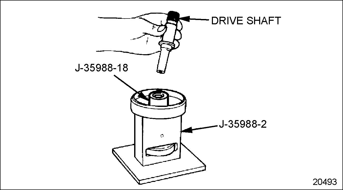
The drive shaft must be installed pressing on the outer bearing race only. Any other attempt at installation may damage the bearings.
Press the drive shaft and bearing assembly into the water pump housing, using J–35988–1 (part of tool set J–35988–C)
until it is seated firmly against the shoulder in the housing.
Form-a-Gasket Sealer must be used sparingly, and kept from the shaft and bearing surfaces. Excessive amounts of Form-a-Gasket Sealer could cause plugging of radiator or cooler core.
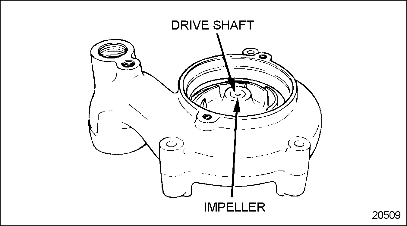
Turn the water pump housing over. Working through the front, apply a coating of Aviation Form-a-Gasket, Form-a-Gasket No. 3 or equivalent to the area where the water pump seal case contacts the pump body. See Figure
"Sealer Installation"
.
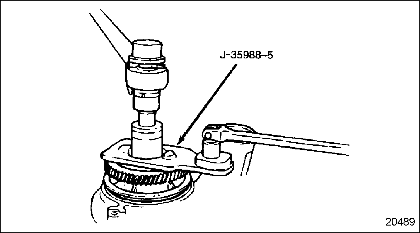
Install the water pump drive gear to the drive shaft, indexing the slot in the gear with the Woodruff key.
NOTICE:
Extension tool (J–35988–3A, part of tool set J–35988–C)
must support the shaft. This is necessary to prevent damage to the bearings when pressing the gear onto the shaft.
Using J–35988–5A (part of tool set J–35988–C)
with a breaker bar to hold the gear and shaft, torque the locknut with a torque wrench to 203-230 N·m (150-170 lb·ft).
Section 4.3.6.1 Assembly Integrity Test
Verify the assembly integrity as follows:
Turn the pump over and install J–35687
into the tapped holes provided in the impeller.
Using a dial indicator with a magnetic base, measure the total run-out of the water pump drive gear at four places, at 90 degree intervals. Maximum allowable run-out is 0.0635 mm (0.0025 in.). See Figure
"Measuring Water Pump Drive Gear Runout (FM)"
.
Figure 28. Measuring Water Pump Drive Gear Runout (FM)
Section 4.3.7 Installation of Front Mounted Water Pump
Install the water pump as follows:
Coat the two seal rings with clean engine oil. Install the larger seal ring to the groove in the water pump housing. Install the smaller seal ring to the groove in the water pump cover. Coat the water pump drive gear with clean engine oil.
Install the water pump to the engine, meshing the water pump drive gear with the bull gear.
Install the three water pump housing-to-gear case cover bolts. Tighten the bolts alternately and evenly to draw the water pump straight into the engine. Torque the bolts to 30-38 N·m (22-28 lb·ft).
Install the water pump cover to the water pump with two bolts. Torque the bolts alternately and evenly to draw the cover straight into the water pump housing. Torque the bolts to 30-38 N·m (22-28 lb·ft).
Slide the coolant hoses into position and tighten the hose clamps.