
The Garrett GTA42 turbocharger is used on all Series 60G automotive engines. See Figure "GTA42 Turbocharger Assembly (Coach)" .
Note: On April 2000, all Series 60 engines with GT40 and GT42 turbochargers were replaced by GTA40 and GTA42 turbos. The GTA turbo has a CHRA (center housing rotating assembly) with a boreless compressor wheel.
|
1. Compressor Housing |
4. Wastegate Actuator |
|
2. Actuator Hose |
5. Turbine Housing |
|
3. Water-cooled Center Housing |
6. V-Band Joints |
Figure 1. GTA42 Turbocharger Assembly (Coach)
The turbocharger is designed to increase the overall power and efficiency of the engine. Power to drive the turbocharger is extracted from the energy in the engine exhaust gas.
The CHRA consists of a turbine wheel and shaft, a compressor wheel, and a center housing that serves to support the rotating assembly, bearings, seals, a turbine housing, and a compressor housing. The center housing has connections for oil inlet, oil outlet, water inlet and water outlet fittings.
The rotating assembly consists of a turbine wheel and shaft assembly, piston ring(s), thrust spacer, compressor wheel, and wheel retaining nut. The rotating assembly is supported on two pressure-lubricated bearings that are retained in the center housing by snap rings. Internal oil passages are drilled in the center housing to provide lubrication to the turbine wheel shaft bearings, thrust washer, thrust collar, and thrust spacer. Internal water passages provide cooling and subsequent protection against oil cooking in the housing.
The turbine housing is a heat-resistant alloy casting that encloses the turbine wheel and provides a flanged engine exhaust gas inlet and an axially located turbocharger exhaust gas outlet. The turbine housing is secured to the turbine end of the center housing. An internal turbine bypass valve, commonly called a wastegate, allows exhaust gas to flow around the turbine wheel. This provides control over the maximum boost pressure.
The wastegate is controlled with a pneumatic actuator mounted on the side of the turbine housing. The Series 60G coach engine turbocharger has an actuator with a single hose port on the top side of the actuator can with a silicon hose that runs to a port on the compressor cover. See Figure "GTA42 Turbocharger Assembly (Coach)" . Air pressure from the compressor outlet is fed through the line to the top side of the actuator, which opens the wastegate valve at a specified pressure.
The turbocharger is mounted on the exhaust outlet flange of the engine exhaust manifold. After the engine is started, the exhaust gases flow from the engine and through the turbine housing causing the turbine wheel and shaft to rotate. See Figure "Schematic Air Flow Diagram (Series 60G Automotive)" .

Figure 2. Schematic Air Flow Diagram (Series 60G Automotive)
The gases are discharged into the exhaust system after passing through the turbine housing. On automotive engines, an oxygen sensor and exhaust temperature sensor are installed within 12 inches of the turbocharger turbine outlet. A harness connects the sensors to the ECM.
The compressor wheel, in the compressor housing, is mounted on the opposite end of the turbine wheel shaft and rotates with the turbine wheel. The compressor wheel draws in clean air, compresses it, and delivers high pressure air through the intake manifold to the engine cylinders.
Oil for lubricating the turbocharger is supplied under pressure through an external oil line extending from the oil filter adaptor to the top of the center housing. Water for cooling the bearing housing is supplied from the oil cooler, and is returned to the top of the thermostat housing. See Figure "Turbocharger Oil/Water Lines Series 60 Gas (Automotive)" .

|
1. Elbow, Oil Drain Tube |
9. Connector, Oil Supply Tube (from oil filter adaptor) |
|
2. Tube, Turbo Oil Drain |
10. Tube Assembly, Turbo Oil Supply |
|
3. Bolt, and Lockwashers, Oil Drain Tube Mounting |
11. Bolt, Oil Supply Tube Clip |
|
4. Gasket, Oil Drain Tube |
12. Clip, Oil Supply Tube |
|
5. Elbow |
13. Gasket, Turbo Exhaust Inlet |
|
6. Clamp |
14. Water Supply Line |
|
7. Nut, and Washer Turbo Mounting |
15. Water Return Line |
|
8. Turbocharger Assembly |
|
Figure 3. Turbocharger Oil/Water Lines Series 60 Gas (Automotive)
From the oil inlet in the center housing, the oil flows through the drilled oil passages in the housing to the shaft bearings, thrust ring, thrust bearing, and backplate or thrust plate. See Figure "Turbocharger Oil Flow Diagram (Series 60G, Automotive)" .

|
1. Compressor Wheel |
6. Shaft |
|
2. Thrust Bearing |
7. Turbine Wheel |
|
3. Backplate |
8. Shaft Bearings |
|
4. Oil Inlet |
9. Oil Outlet |
|
5. Center Housing |
10. Water passages |
Figure 4. Turbocharger Oil Flow Diagram (Series 60G, Automotive)
The oil returns by gravity to the engine oil pan through an external oil line extending from the bottom of the turbocharger center housing to the cylinder block. Water flows through the bearing housing in a U-shape flow path, removing heat generated by the hot exhaust gas in the turbine.
To determine if repair is possible or replacement of the turbocharger is necessary perform the following procedure. See Figure "Flowchart for Repair or Replacement of Turbocharger (Series 60 Gas, Automotive)" .
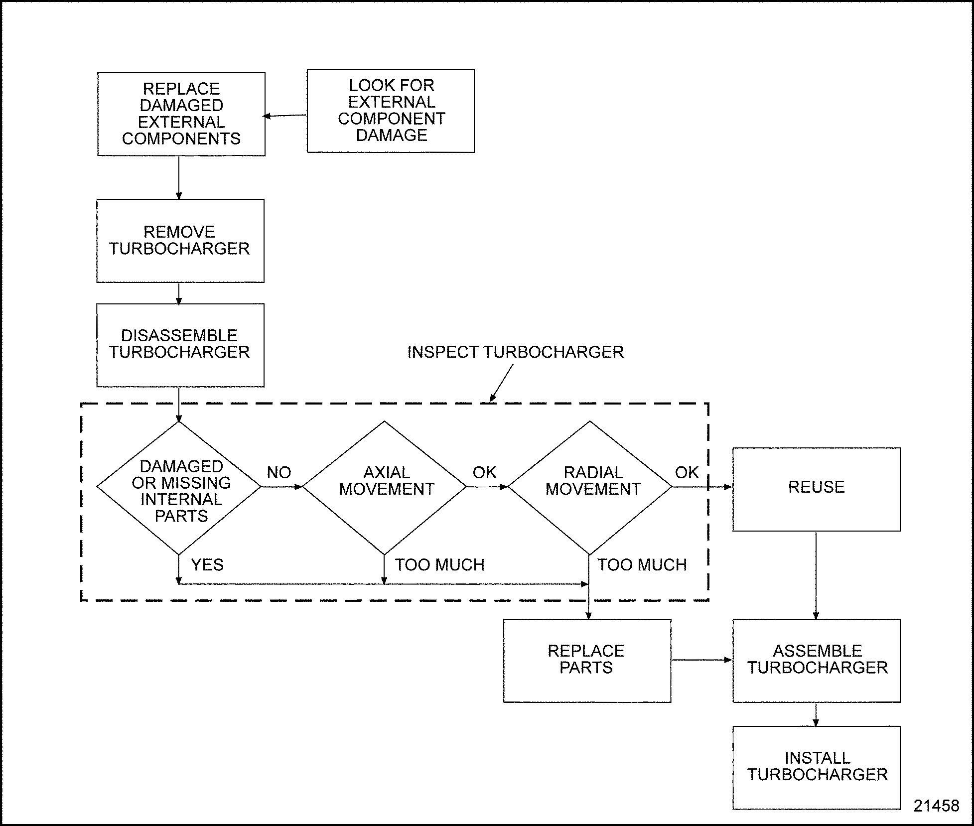
Figure 5. Flowchart for Repair or Replacement of Turbocharger (Series 60 Gas, Automotive)
Cleaning the turbocharger is not necessary before removal.
|
PERSONAL INJURY |
|
To avoid injury from hot surfaces, wear protective gloves, or allow engine to cool before removing any component. |
Prior to removal, visually check for:
To remove the turbocharger, perform the following:
NOTICE: |
|
Do not attempt to remove carbon or dirt buildup on the compressor or turbine wheels without removing the turbocharger from the engine. If chunks of carbon are left on the blades, an unbalanced condition will exist and subsequent failure of the bearings will result if the turbocharger is operated. However, it is not necessary to disassemble the turbocharger to remove dirt or dust buildup. |
Note: Be sure to drain coolant before removing water lines from bearing housing.
|
PERSONAL INJURY |
|
To avoid injury from improper use of chemicals, follow the chemical manufacturer's usage, handling, and disposal instructions. Observe all manufacturer's cautions. |
Disassemble the turbocharger as follows:
Note: Clean the exterior of the turbocharger with a non-caustic cleaning solvent before disassembly.
NOTICE: |
|
Exercise care when removing the compressor housing and turbine housing to prevent damage to the compressor and turbine wheels. |

|
1. Compressor Housing |
3. Turbine Housing |
|
2. Compressor Housing and Rotating Assembly |
4. V-Band Couplings |
Figure 6. GTA42 Turbocharger
Damage can result from a contaminated exhaust system. Any debris left in the exhaust system after service work can fall back into the exhaust wheel. If large enough, these particles may cause turbine wheel damage at initial engine startup. The exhaust manifold and exhaust piping attached to the turbocharger should also be inspected for debris and cleaned, if necessary, before being installed.
Any time the charge air cooler is removed, all charge air cooling system components must be inspected to make sure they are clean and free of any casting slag, core sand, welding slag, or any other contaminants that could break free during engine operation and damage the turbine wheel.
Inspect the disassembled turbocharger, discarding any damaged parts, in the following manner:

Figure 7. Checking Bearing Axial End Play
Due to the internal construction of the GTA42 bearing housing, access to the shaft through the oil drain is not possible. Therefore, radial movement cannot be accurately measured to determine the condition of radial turbine bearings.
To determine the general condition of the radial bearings, check radial end play after the turbocharger is cleaned and assembled. Push on the end of the shaft, towards the side of the compressor (or turbine) housing. If the wheel contacts either housing, the radial bearings may be worn out, and the CHRA should be replaced (be sure to check if the housing is seated and installed correctly also).
The CHRA is serviced by replacement only. Do not attempt disassembly of the CHRA, as possible shaft imbalance and damage may result.
This procedure provides a method for verifying proper wastegate calibration.

|
1. Hose to Wastegate Actuator |
4. Supply Air Shutoff Valve |
|
2. Vent Valve |
5. Pressure Regulator |
|
3. Pressure Gage |
6. Shop Air Supply |
Figure 8. Checking Wastegate Calibration for the Series 60G Automotive Engine
|
Model |
Rating |
Set Pressure Travel at 1.0 mm (0.04 in.) Rod |
|
Coach |
330 Hp |
165 kPa (24 psi) |
NOTICE: |
|
For genset turbochargers, NEVER apply pressure to bottom part of actuator can. Damage to actuator may result. |
This procedure describes the removal of a actuator currently mounted on a turbocharger, and the replacement with a new service actuator. Further adjustment of the actuator will be necessary to achieve the correct pressure setting, listed in Table "Series 60G Wastegate Calibration Pressure at 0.04 in. Rod Travel" .
NOTICE: |
|
Never remove the rod end from the wastegate lever pin unless pressure is applied to the top side actuator port; otherwise, damage to the actuator diaphragm may result. |
Replace wastegate actuator as follows:
This procedure describes the set pressure adjustment of an installed wastegate actuator. Before following this procedure, first check the actuator set pressure to see if adjustment is needed refer to "6.6.4 Checking Wastegate Calibration for the Series 60G Automotive Engine" .

|
1. Wastegate Actuator Assembly |
4. Adjusting Rod End |
|
2. Locking Collar |
5. Retainer Clip |
|
3. Jam Nut |
6. Wastegate Lever and Pin Assembly |
Figure 9. Wastegate Adjustment
NOTICE: |
|
For genset actuator, never apply pressure to the bottom side of actuator port. Damage to the actuator may result. |
Use the following procedure to assemble the turbocharger:
NOTICE: |
|
As the parts are assembled, cover the openings to prevent entry of dirt or other foreign material, which may cause component damage. |
NOTICE: |
|
Failure to properly orient the Tee-bolt end of the clamp can result in an exhaust leak, turbine wheel damage or both. |
Note: Do not pull a misaligned turbine housing into alignment with the V-band coupling. The parts must be aligned and seated first.
NOTICE: |
|
The 5/8 in. hex-head turbine housing bolts replaced 3/8 in. hex-head bolts. The 5/8 in. hex-head bolts are required to ensure sufficient clamp load. |
To install the turbocharger:
|
PERSONAL INJURY |
|
To avoid injury from the sudden release of a high-pressure hose connection, wear a face shield or goggles. |
NOTICE: |
|
Do not use any type of lubricant on the inside of any air inlet hose or on the hose contact surfaces of the turbocharger compressor housing, CAC ducting or the intake manifold. |
| Series 60 Service Manual - 6SE483 |
| Generated on 10-13-2008 |