
An oil seal is fitted between each end of the crankshaft and the bores of the flywheel housing and gear case cover to retain the lubricating oil in the crankcase. In certain applications, the seal must also prevent transmission oil from migrating into the engine. Seals are pressed into the bores after the housing or cover is assembled to the engine. See Figures "Crankshaft Rear Oil Seal" and .
Figure 1. Crankshaft Rear Oil Seal

Figure 2. Crankshaft Front Oil Seal
Current seals feature a lay down sealing lip of low-friction PTFE with unidirectional spiral pumping grooves. An outer dust-exclusion lip keeps airborne dirt away from the primary sealing lip. The sealing lip does not touch the crankshaft, because an integral wear sleeve provides the running surface and protects the lip during installation. A separate replacement wear sleeve is not needed. The wear sleeve and outer carrier are joined together, forming a unitized seal assembly.
Because of the spiral grooves on the sealing lip, a front crankshaft seal will leak if installed at the rear, and a rear crankshaft seal will leak if installed at the front.
Wet-flywheel-housing applications require a double-lip rear seal to prevent transmission oil from migrating into the engine. This seal is similar to the single lip seals except for the extra lip, and the wear sleeve and outer carrier are not joined together.
NOTICE: |
|
Failure to use the correct seal according to location on the engine or according to flywheel housing type or application may result in seal damage, oil leakage, or damage to the engine and the vehicle or equipment into which it is installed. |
All engines may be serviced with the current-production front seal. However, engines built before serial number 06R0491683 were built with a different design of rear crankshaft seal (dry flywheel housings only). This seal may not be serviced with the current rear seal because the current rear seal requires a cast-in rib on the flywheel housing and block to direct additional oil to the seal for cooling. See Figures "Cast-in-Rib Front View" and .

|
1. Rib Location |
Figure 3. Cast-in-Rib Front View

|
1. Rib Location |
Figure 4. Cast-in-Rib Rear View
Service replacements of the old design rear seal are shipped as an assembly consisting of a seal installed over a separate wear sleeve. The sleeve is pressed onto the crankshaft hub with the seal to provide a new running surface. This sleeve must be installed with replacement seals to prevent seal damage or oil leakage.
To determine if replacement is necessary, perform the following procedure. See Figure "Flowchart for Replacement of Crankshaft Oil Seal" . To determine whether flywheel housing runout is excessive,refer to "1.18.3.1 Test for Flywheel Housing Bore Concentricity" .

Figure 5. Flowchart for Replacement of Crankshaft Oil Seal
Perform the following procedures to remove the crankshaft seal from the gear case cover or flywheel housing if the cover or housing has been removed from the engine.
NOTICE: |
|
Due to the possibility of damage to the crankshaft oil seals, any time the gear case cover or flywheel housing is removed from the engine, the crankshaft oil seals must be replaced. |

Figure 6. Crankshaft Oil Seal Removal
Note: Crocus cloth may be used to remove dirt and rust and to clean up the high spots from the surface of the crankshaft and gear case cover or flywheel housing bore. Clean the contact surfaces thoroughly.

Figure 7. Crankshaft Wear Sleeve Remover Tool
The crankshaft oil seals may be taken out without removing the gear case cover or flywheel housing. This may be done by using crankshaft oil seal removal tool (J–41329) .
Note: To assist seal removal, thoroughly clean all rust and dirt from the crankshaft surface. Application of penetrating oil to the wear sleeve and crankshaft hub may also aid seal removal.
Remove the seal as follows:

Figure 8. Removing Front Crankshaft Oil Seal from Gear Case Cover or Flywheel Housing
Note: Use all six holes to ensure removal is successful. Drive screws carefully, the threads can strip easily when using an electric driver.
Note: Seals may be difficult to remove due to debris on the crankshaft preventing the wear sleeve from passing over the crankshaft. Push the seal 1/8 inch, clean the crankshaft surface thoroughly and repeat the removal procedure. Application of penetrating oil to the wear sleeve and crankshaft hub may also aid seal removal.
Note: Crocus cloth may be used to remove dirt, rust and to clean up the high spots from the surface of the crankshaft and gear case cover bore. Thoroughly clean the contact surfaces.
If the seal that was removed used a separate wear sleeve, the old wear sleeve must also be removed. Use the following procedure to remove wear sleeve.
Note: Crocus cloth may be used to clean up the high spots from the surface of the crankshaft.
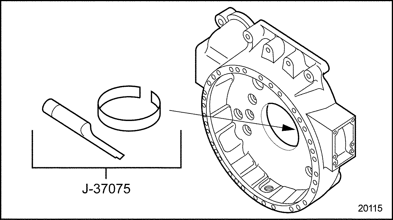
Figure 9. Rear Oil Seal Wear Sleeve Removal
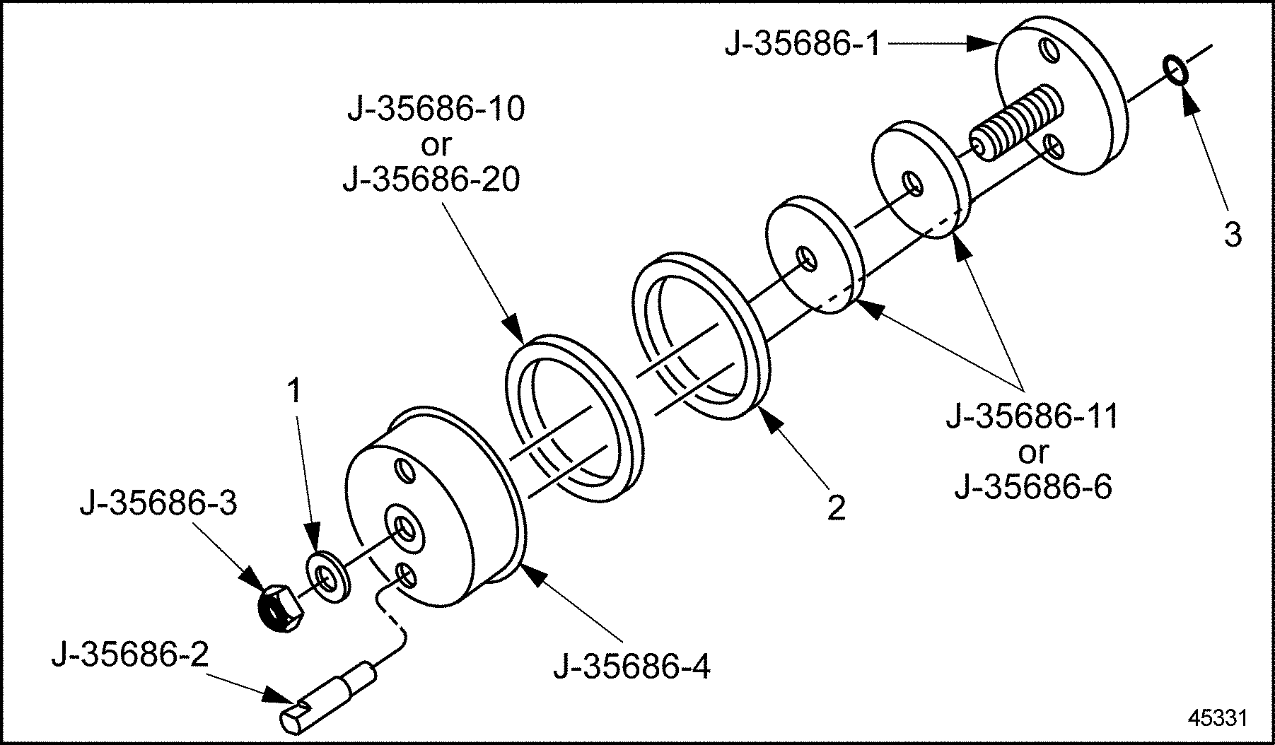
All replacement oil seals provide a replacement wear surface at the point of contact with the sealing lip. The oil seal assembly is installed using the crankshaft oil seal sleeve installation tool set (J–35686–B) .
See Figure "Crankshaft Oil Seal and Sleeve Installation Tool Set (J–35686–B)" for the general installation tool set.
The collar and spacer usage is dependant on the part number of the seal to be installed. See Table "Crankshaft Seal Tool Application" .
|
1. Thrust Bearing |
3. Guide Stud Retaing O-ring |
|
2. Crankshaft Seal |
Figure 10. Crankshaft Oil Seal and Sleeve Installation Tool Set (J–35686–B)
|
Crankshaft Seal Application |
Seal Part Number |
Collar |
Spacers |
|
Front |
23518355 |
J–35686–20 |
J–35686–11 |
|
Rear, Dry Housing |
23516969 (assembly contains seal part no. 23501544) |
J–35686–10 |
J–35686–6 and J–35686–11 |
|
Rear, Dry Housing |
23519651 |
J–35686–20 |
J–35686–6 and J–35686–11 |
|
Rear, Wet Housing |
23513578 |
J–35686–10 |
J–35686–6 and J–35686–11 |
|
NOTICE: |
|
Ensure that the crankshaft hub and bolt surface, gear case cover, flywheel housing bore and contact surfaces of the installation tools are free of dirt, grit, rust or raised metal. Clean thoroughly with crocus cloth if needed. Ensure that an old wear sleeve is not installed onto the crankshaft hub. Refer to "1.8.4 Removal of Wear Sleeve from Crankshaft Hub" for wear sleeve removal instructions. |
|
NOTICE: |
|
The incorrect installation of the oil seal will cause immediate seal leakage, or will reduce the life of the seal significantly. |
Perform the followings steps to install the front and rear oil seals and sleeves:
|
NOTICE: |
|
Failure to lubricate the outside of the seal and the inside of the bore prior to installation may damage seal causing seal to leak. |

Figure 11. Spacer Installation
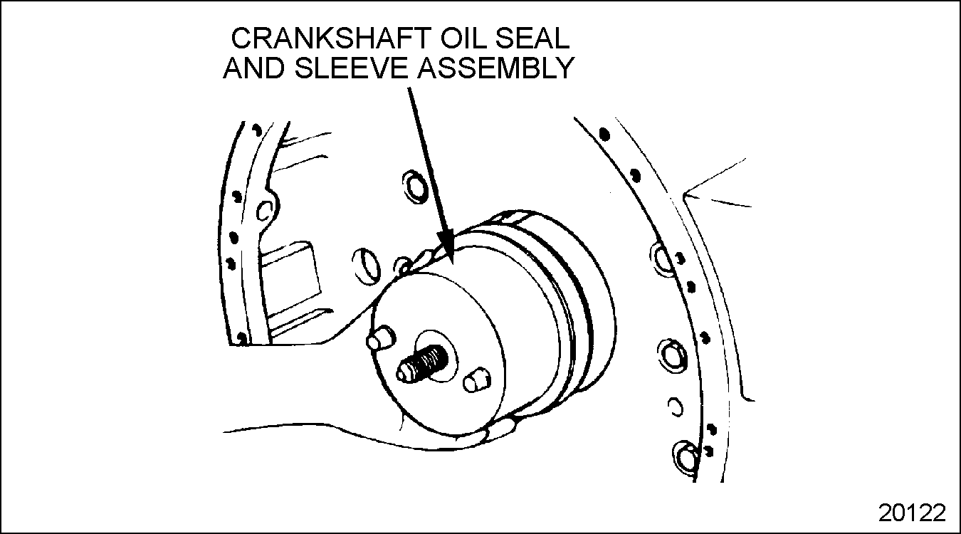
Figure 12. Oil Seal and Sleeve Installation

Figure 13. Thrust Bearing Installation
| Series 60 Service Manual - 6SE483 |
| Generated on 10-13-2008 |