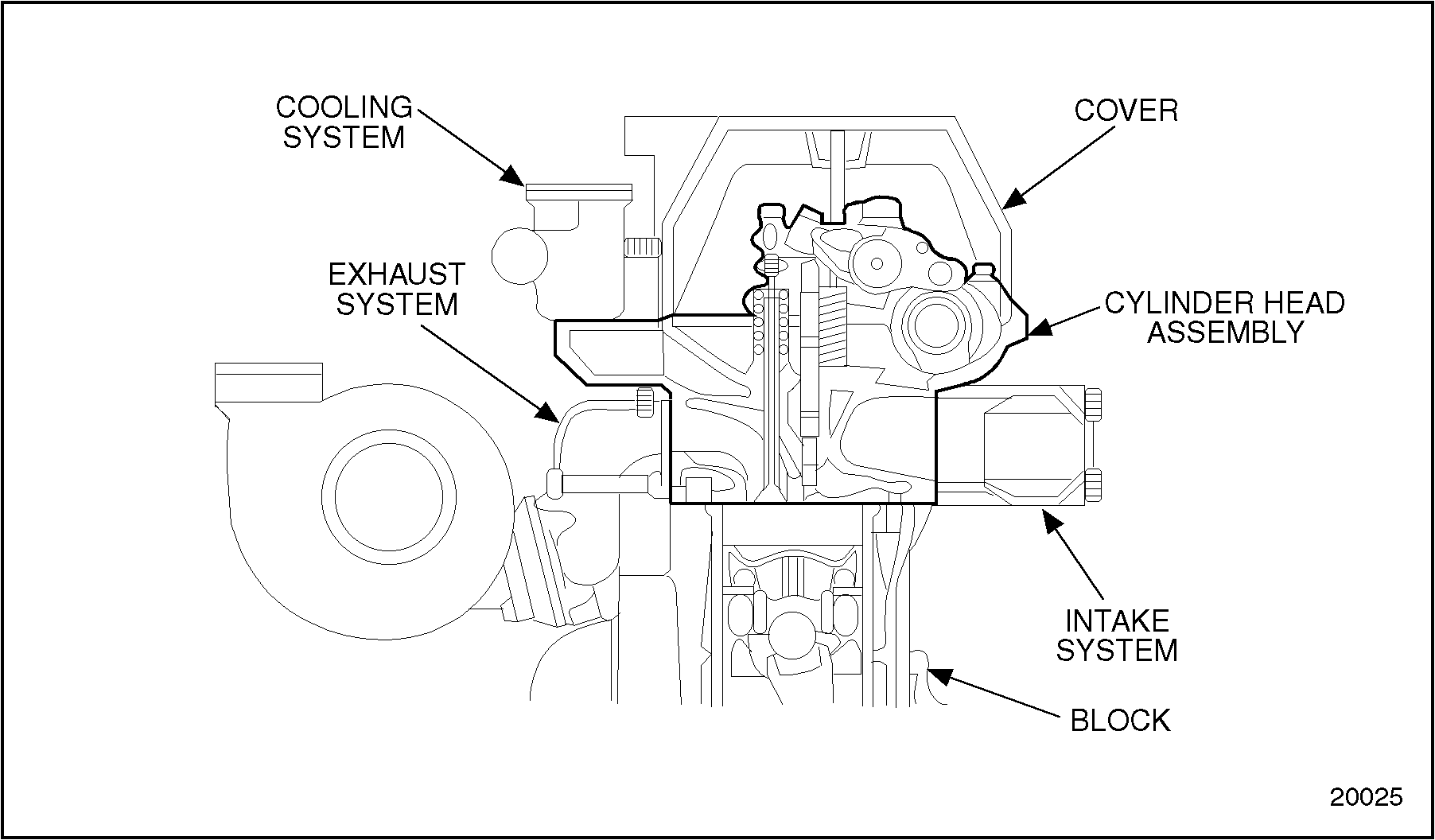
The Series 60 cylinder head combines intake and exhaust valve porting and fuel injector seats with water jacketing to cool the ports, injectors and combustion chamber area. See Figure
"Cylinder Head Assembly and Mating Components"
.
Figure 1. Cylinder Head Assembly and Mating Components
With the overhead camshaft design, the cylinder head assembly includes:
Cylinder head
Valve and injector operating mechanism
Injector, valve guide and related parts
Camshaft and camshaft bearings
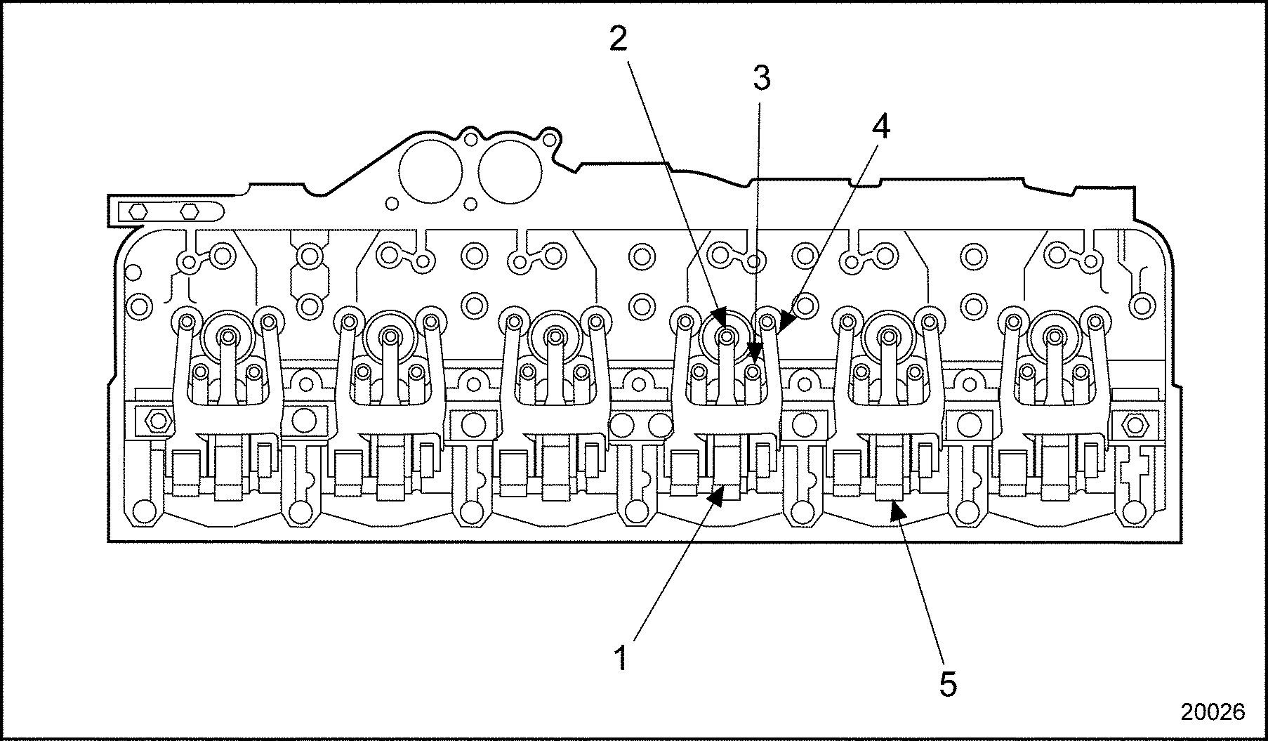
The nested roller follower type rocker arms transmit camshaft motion directly to the valves and injectors. See Figure
"Cylinder Head Assembly"
.
Figure 3. Cylinder Head Assembly (Series 60G Engine)
The porting within the cylinder head is cross-flow, with intake and exhaust ports on opposite sides for minimum restriction and maximum exposure to coolant flow. Four valves are used per cylinder, two intake and two exhaust. See Figure
"Intake and Exhaust Valve Porting"
.
Figure 4. Intake and Exhaust Valve Porting
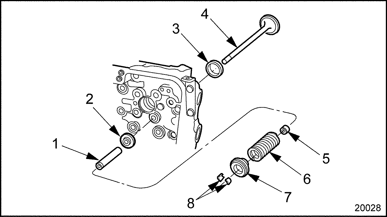
Replaceable valve guides, valve spring seats, valve stem seals, valve rotators and valve seat inserts are used on all valves. See Figure
"Valve Guides and Related Parts"
.
1. Valve Guide
5. Valve Stem Oil Seal
2. Valve Spring Seat
6. Valve Spring
3. Valve Seat Insert
7. Valve Rotator
4. Valve
8. Valve Keepers
Figure 5. Valve Guides and Related Parts
Copper injector tubes extending through the cylinder head water jacket are required for the fuel injectors. The tubes are directly exposed to the coolant. An O-ring seals the injector tube upper end in the recess. The lower end of the injector tube must be expanded and flared during the installation process to contain a tight fit in the firedeck bore. A beveled seat machined in the tube provides a compression-tight seal when the injector is seated, as well as affording effective heat transfer facilitating injector cooling. Refer to "2.4 N2 Fuel Injector Tube and O-Ring"
.
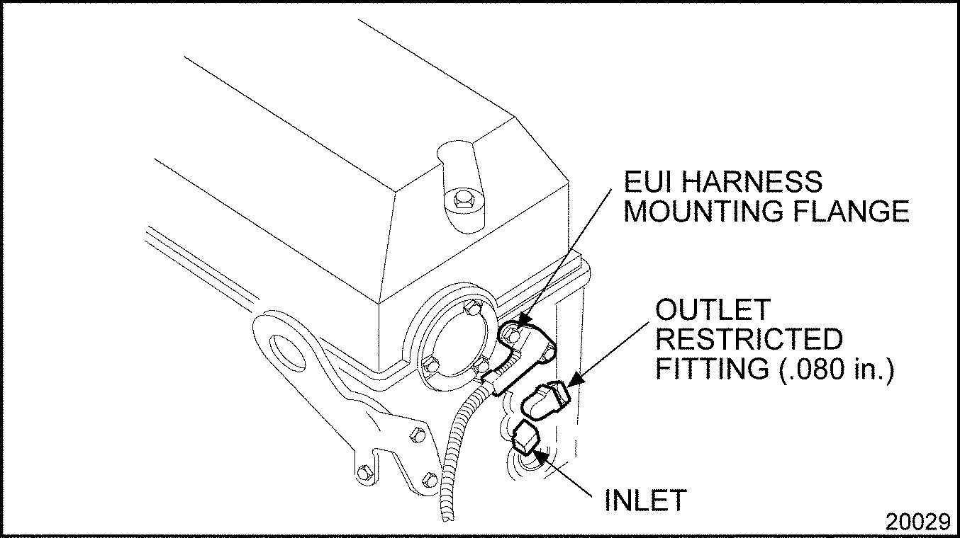
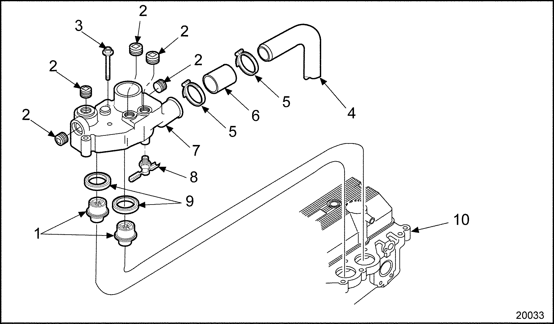
Fuel galleries machined into the head supply fuel under fuel pump pressure to all injectors, and excess fuel is returned to the fuel tank. The fuel gallery outlet (restricted) fitting is installed in the rear of the cylinder head. See Figure
"Fuel Gallery Inlet and Outlet Fittings"
.
Figure 6. Fuel Gallery Inlet and Outlet Fittings
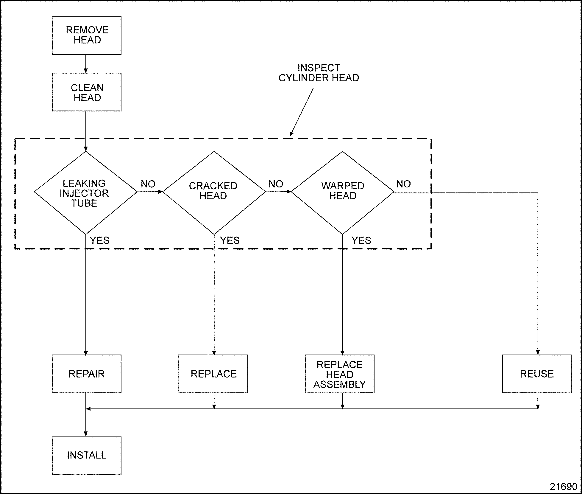
Section 1.2.1 Repair or Replacement of Cylinder Head
Figure 7. Flowchart for Repair or Replacement of Cylinder Head
Section 1.2.2 Removal and Cleaning of Cylinder Head
Because optional and accessory equipment varies with the engine application, this procedure covers only the basic engine. If the engine is equipped with accessories that affect cylinder head removal, note the mounting details of each to assure correct installation at reassembly.
Disconnect the turbocharger coolant supply (if water-cooled), oil supply and drain lines, and remove the turbocharger if necessary. See Figure
"Turbocharger Oil Lines"
.
1. Elbow, Oil Drain Tube
10. Connector, Oil Supply Tube
2. Bolt, Mounting Bracket
11. Tube Assembly, Turbo Oil Supply
3. Bolt, Oil Drain Tube Clip
12. Clip, Oil Supply Tube
4. Tube, Turbo Oil Drain
13. Bolt, Oil Supply Tube Clip
5. Bolt, Oil Drain Tube Mounting
14. Connector, Oil Supply Tube (to turbocharger)
6. Gasket, Turbo Oil Drain Tube
15. Gasket, Turbo Exhaust Inlet
7. Nut, Turbo Mounting
16. Clip, Oil Drain Tube
8. Washer, Turbo Mounting
17. Bracket, Oil Drain Tube Clip Mounting
9. Turbocharger Assembly
18. Nut, Oil Drain Tube Clip
Figure 8. Turbocharger Oil Lines
Seal the turbocharger compressor inlet and discharge with covers or masking tape. Plug the oil supply fitting in the turbocharger housing.
Note: Using the camshaft gear pilot tool (J–35906)
pull the camshaft gear and thrust plate forward in the gear case until there is approximately a 6.35 mm (1/4 in.) gap between the cylinder head and the diamond-shaped camshaft thrust plate seal when removing the cylinder head. See Figure
"Positioning Camshaft Thrust Plate"
.
Figure 14. Removing Fuel from Cylinder Head Internal Passages
EYE INJURY
To avoid injury from flying debris when using compressed air, wear adequate eye protection (face shield or safety goggles) and do not exceed 276 kPa (40 psi) air pressure.
Blow low pressure compressed air into the inlet fitting for 20 to 30 seconds or until all of the fuel is purged from the cylinder head.
Remove the harness mounting flange from the rear of the cylinder head and carefully remove the harness from the head by pulling the harness through the hole in the cylinder head. See Figure
"Fuel Gallery Inlet and Outlet Fittings"
.
NOTICE:
To avoid possible damage to the injector spray tips, remove the injectors before lifting the head from the block. If the injectors are not removed, handle the head carefully when it is off the block and support the head fire deck on wooden blocks.
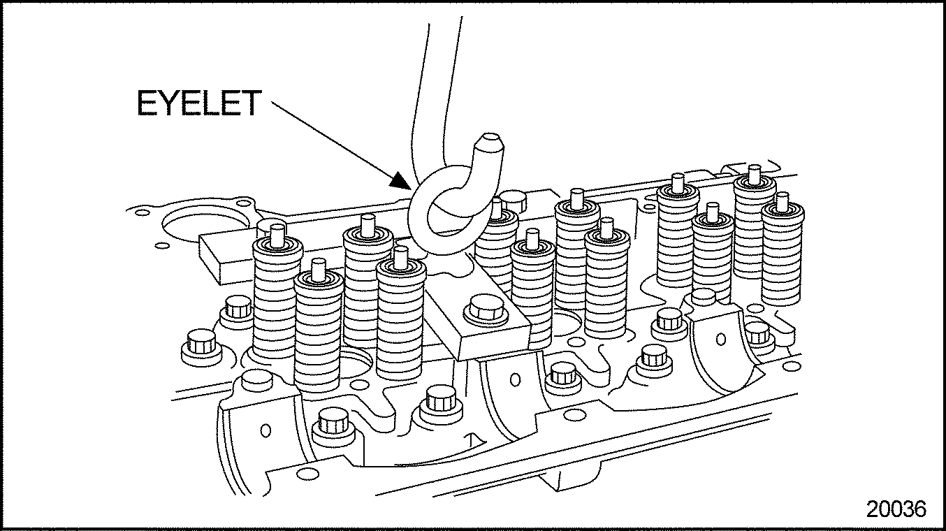
Attach a suitable lifting hook to the eyelet in the lift bracket, and lifter the cylinder head off the engine. See Figure
"Cylinder Head Removal"
.
Figure 16. Cylinder Head Removal
Drain the engine lubricating oil, refer to "14.6.1 Lubricating Oil"
, to remove any coolant that may have drained into the oil pan when the water jacket was opened. Remove any coolant from the cylinder bores.
Section 1.2.3 Cleaning of Cylinder Head
Clean the cylinder head as follows:
Keep parts segregated according to original position to assure proper reassembly, if parts are to be reused.
Remove all threaded plugs.
Steam clean the cylinder head once it has been stripped.
To avoid injury from flying debris when using compressed air, wear adequate eye protection (face shield or safety goggles) and do not exceed 276 kPa (40 psi) air pressure.
Clean the camshaft and camshaft bearings, valves, springs, valve rotators and rocker shafts in fuel oil and blow dry with compressed air.
Clean the rocker arm assemblies.
Section 1.2.3.1 Inspection of Cylinder Head
The following steps must be performed before inspecting the cylinder head:
Replace the plugs removed for cleaning. If the old plugs are reused, coat the plugs with Loctite® PT-7260
, pipe sealant with Teflon, or equivalent.
Note: If both front fuel galley plugs have been removed, it will be necessary to replace both plugs.
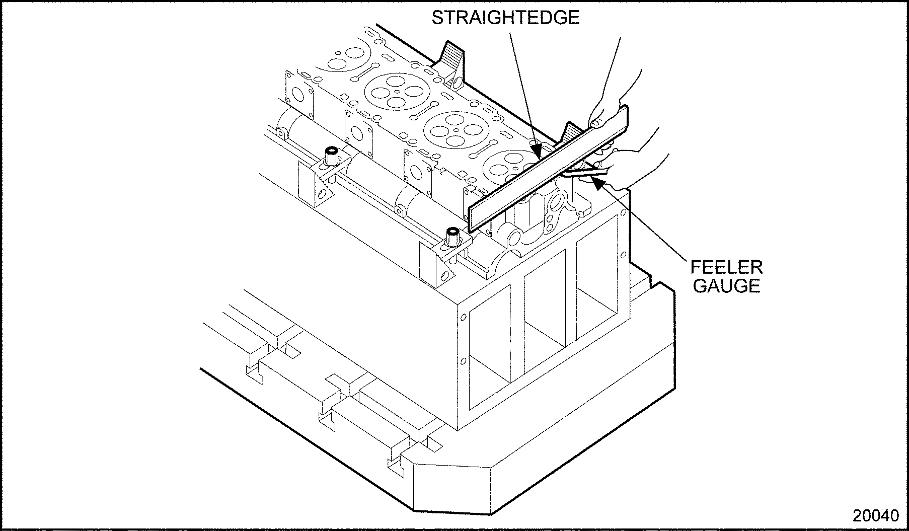
Section 1.2.3.3 Inspection and Rework for Firedeck Straightness
The large mass and length of the head casting may contain longitudinal warp after it is unbolted and removed from the engine block. At the time of factory manufacture, the longitudinal warp is normalized by using a fixture and clamping the casting during machining. The casting is placed in a fixture and clamped from its locating surfaces (datums). When unclamped, the head casting resumes its original shape until it is bolted and tightened to the engine block.
Inspect the bottom (firedeck) of the cylinder head for straightness as follows:
The natural warp contained in the casting must be considered when inspecting firedeck straightness with the head unbolted and unclamped. Natural warpage is not a cause for correction. The firedeck (unclamped) must be straight within 0.279 mm (0.011 in.) front-to-rear and 0.076 mm (0.003 in.) side-to-side. Cylinder head specifications are listed in Table
"Cylinder Head"
.
If the cylinder head flatness is outside of the specifications, Detroit Diesel Corporation recommends replacing the cylinder head.
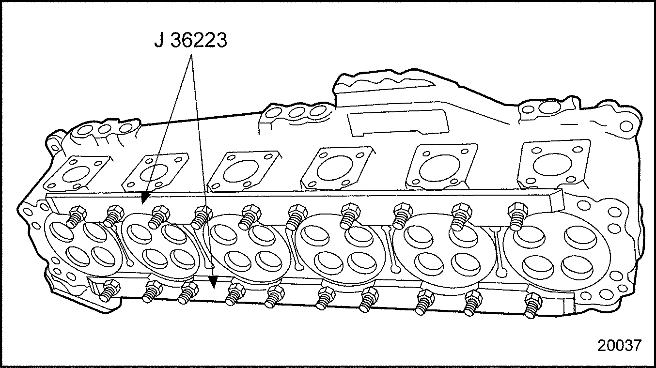
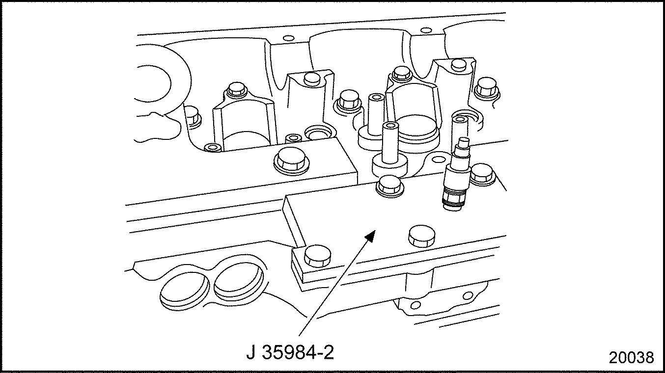
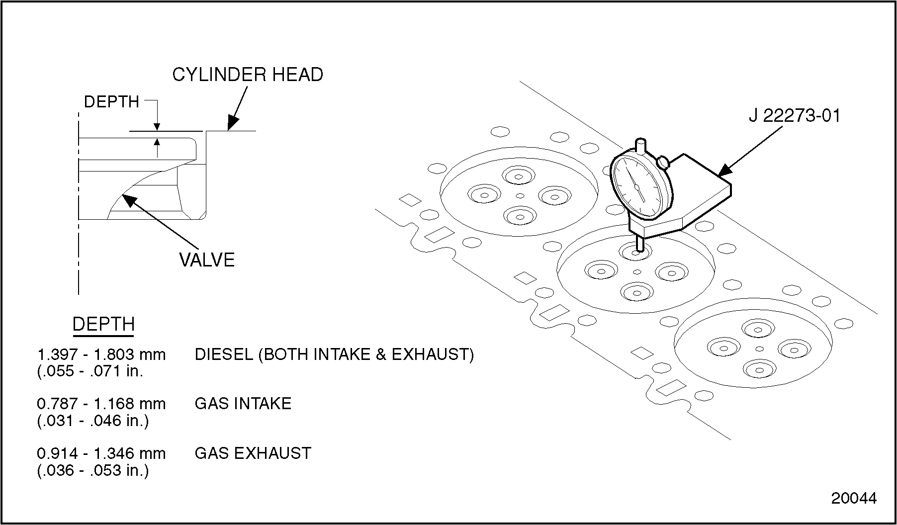
Section 1.2.3.4 Verification of Countersink Geometry
To verify countersink geometry, perform the following steps.
Figure 22. Valve Head-to-Cylinder Head Measurement
Section 1.2.3.5 Inspection and Reworking of Head Bolt Counterbore
To assure clean and non-brinnelled cylinder head bolt counterbores, use J–38189
to resurface the head bolt washer area.
The procedure and steps for proper use of the tool are as follows:
NOTICE:
There must be no space between the bottom of the cylinder head and the table top to properly resurface the counterbores.
Place the cylinder head on a solid flat surface (preferably a steel table top) that completely covers the bottom of head.
NOTICE:
Proper use of the J–38189
is important. Failure to use J–38189
properly may result in an incorrect counterbore depth.
Protect the valve springs and injector counterbore to keep any loose metal shavings from getting into valve springs and counterbore during cutting operation.
With cylinder head on a flat surface using the 1/8 in. hex wrench supplied with tool, loosen the stop collar and cutter to permit sliding on pilot.
Starting at the front of the cylinder head, place the pilot of the cutter into a cylinder head bolt hole until the pilot contacts the flat surface beneath the cylinder head.
Allow the cutter to contact the counterbore surface. Lock the stop collar while against the cutter. The cutter now will resurface the counterbore 0.508 mm (0.020 in.).
Remove the tool and place a 0.020 in. feeler gage between the cutter and the locked stop collar.
With feeler gage in place, lock the set screw of the cutter, then remove the feeler gage and loosen the set screw on the stop collar and slide it down tight against the cutter and retighten.
Perform the following steps to resurface the counterbore 0.508 mm (0.020 in.):
Using a drill motor with a 1/2 in. chuck and a maximum
of 450 r/min and a suitable cutting oil to prolong the life of the cutter and to lubricate the pilot turning in bolt hole,
Apply a moderate pressure on the drill motor, continue cutting operation until pilot bottoms on flat surface and then do not stop drill motor until after being lifted from cutting surface. This is to eliminate surface marks.
Note: The J–38189
tool pilot has a shoulder stop that will not allow the cutter to remove material in excess of the Detroit Diesel Corporation specifications.
If some of the bolt holes do not clean up completely, continue resurfacing remaining holes, repeating the operation in. 0.005 in. increments. This will clean up any holes that may not have cleaned up completely during the first cut.
After all counterbores have been resurfaced, remove any loose cutting chips.
Steam clean the complete cylinder head.
After steam cleaning, inspect the cylinder head for any remaining chips.
Reinstall the cylinder head assembly, using 38 of the new ground head bolt washers.
Section 1.2.4 Assembly of Cylinder Head
Perform the following steps for cylinder head assembly:
EYE INJURY
To avoid injury from flying debris when using compressed air, wear adequate eye protection (face shield or safety goggles) and do not exceed 276 kPa (40 psi) air pressure.
NOTICE:
If the cylinder head is to be replaced, the new head must be thoroughly cleaned before installation to remove all rust and preventive compound, especially from the fuel and oil galleries. This can be done by immersion in a bath of fuel oil or mineral-spirits-based solvent and scrubbing out all openings with a soft bristle brush. When clean, blow the head dry with compressed air.
Install new precoated pipe plugs or coat the used plugs with pipe sealant with Teflon, PT-7260
, or equivalent. Refer to "Additional Information"
1.A, "Engine Plug and Dowel Charts" for specifications.
Install all of the required cup plugs using a good grade of non-hardening sealant, such as Loctite® 620 or equivalent, on the cup plugs. Use cup plug installation tool set (J–35653)
. Refer to "Additional Information"
1.A, "Engine Plug and Dowel Charts" for specifications.
Ensure that all cup and pipe plugs on the front face of the cylinder head are flush or below the surface.
Perform the following steps for cylinder head installation:
Ensure piston domes and the cylinder head and cylinder block firedeck surfaces are clean and free of foreign matter. Inspect the head bolt holes in both block and head for the presence of oil, water, dirt, or damaged threads, clean or retap as necessary.
Note: Effective with engine serial number 06R0766277 Series 60 engines will use a new cylinder head gasket. The new gasket will be identified with a new part number and is a darker shade of gray with a woven appearance. The new gasket must be used with the new style cylinder head bolts.
If gasket part number 23530421 is being used, the cylinder head bolts must not be reused. Failure to install new style bolts when using this gasket may result in improper clamp load, which could cause gasket failure and severe engine damage.
Install the head bolts with special hardened washers, lubricating the threads and bolt-head contact areas with a small amount of International Compound #2®, or equivalent.
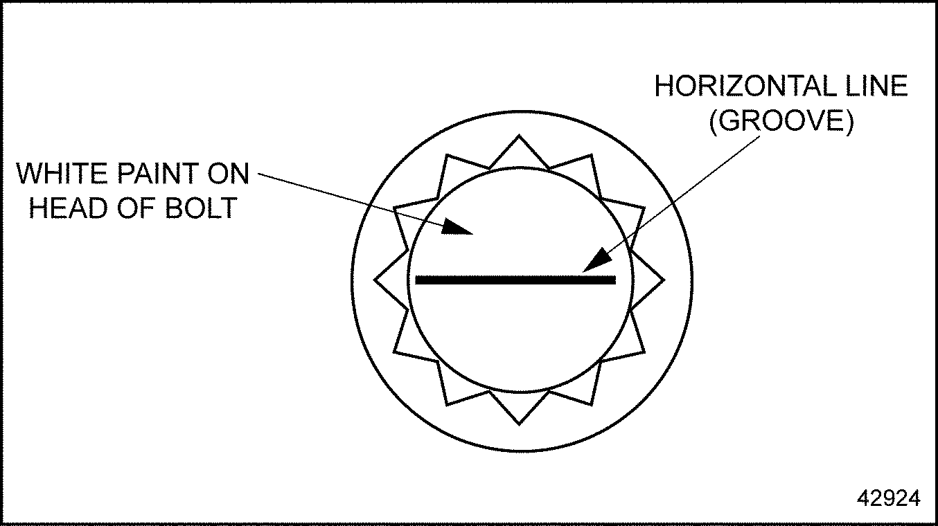
For engines built after September 2002 a new style cylinder head bolt will be used for all Series 60 On-Highway engines. This bolt may or may not be identified with white paint. The new bolt will be identified with a groove on top of bolt. See Figure
"Bolt Identification For Series 60 Engines Built After September 2002"
. Torque the new head bolts to 298 N·m (220 lb·ft). There is no change to the procedure other than the new torque value. The new head bolt can be used with the former cylinder head gaskets, the former head bolts cannot be used with the new head gasket. Former and new bolts must not be mixed.
Figure 25. Cylinder Head Bolt Tightening Sequence
NOTICE:
The white paint identification for the new head bolts may or may not be applied to the bolt head.
Figure 26. Bolt Identification For Series 60 Engines Built After September 2002
NOTICE:
Failure to repeat the cylinder head bolt torque tightening sequence can result in some head bolts losing their torque when others are tightened resulting in insufficient clamp load.
Repeat the torque sequence to verify all of the head bolts are torqued to specification.
Note: If a cylinder head other than the one removed from the engine, or if a resurfaced cylinder head is being installed, the three nuts retaining the adjustable idler gear must be loosened before installing and torquing the camshaft drive gear retaining bolt.
NOTICE:
The camshaft drive gear-to-adjustable idler gear lash must be measured/adjusted before the rocker arm shaft assemblies are installed.
Feed the injector harness wires through the opening at the rear of the cylinder head. Secure the harness mounting flange to the cylinder head by torque the bolts to 10-15 N·m (7-11 lb·ft).
Clean the coolant outlet surfaces of the head and thermostat housing.
With the thermostats seated in the housing counterbores, install the housing to the cylinder head, torque the housing bolts to 58-73 N·m (43-54 lb·ft). Connect the radiator or heat exchanger and bypass hose couplings and vent line.
Clean the exhaust manifold and turbocharger joint surfaces and install the turbocharger with a new gasket. Refer to "6.5.7 Installation of Turbocharger"
. If turbocharger is water cooled, connect coolant supply and return lines.